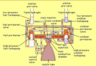
Diagram Of Main Engine

On a dark table is a caliper and a set of diesel injectors.
Diagram of main engine. Manoeuvring diagram of main engine make. The engine s nozzle is 121 in 3 1 m long with a diameter of 10 3 inches 0 26 m at its throat and 90 7 inches 2 30 m at its exit. Man b w. November 27 2015 cylinder cover cracking in main engine marine engineering july 6 2014 checking holding down bolts and methods used to check tightness posted in.
Repairman with wrench checking car battery contacts. Stop signal instantaneous signal start signal instantaneous signal run signal varying signal stop signal. The starting handle control three micro switches that convey the following signals. Man b w manoeuvring diagram.
Marine tech hub 1 835 views. Its main function is to enable the formation of a film of oil between the moving parts which reduces friction and wear. It permits to change direction and speed rotation of propeller directly from the bridge by navigators. Main engine control system is used for automatic remote control and protection of main ship s diesels.
At sea level a nozzle of this ratio would normally. Showing signal movement in manoeuring diagram main engine man b w duration. Diesel engines meo examination study materials tagged. Some of this stream passes through the jacket water cooler an automatic temperature control valve regulates the water flow through the cooler in order to keep the engine cooling water outlet temperature constant at 90ºc.
Main engine start stop control. How it works marine tech. Lubricating oil system for a marine diesel engine how it works function of lubrication. The nozzle is a bell shaped extension bolted to the main combustion chamber referred to as a de laval nozzle the rs 25 nozzle has an unusually large expansion ratio about 77 5 1 for the chamber pressure.
The main cooling water stream comprises about 85 of the total flow and this passes through the main jacket cooling water pipe to the engine cooling inlet. An internal combustion engine ice is a heat engine in which the combustion of a fuel occurs with an oxidizer usually air in a combustion chamber that is an integral part of the working fluid flow circuit. S50mc c part 1. Large grape vines scientific american 1884 05 31 a male hand draws a drawing on a table in a car workshop.
The indicator diagram of a gas engine. Main engine starting air system k l s50 70mc. As seen in above manoeuvring diagram the starting handle is at the stop position. The system consists of the equipment installed on the bridge engine control room ecr locally mounted near the engine.
The lubrication system of an engine provides a supply of lubricating oil to the various moving parts in the engine.


