Asco 8210g95 120v Wiring Diagram

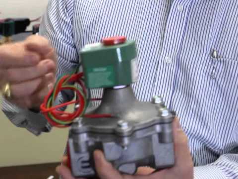
How To Troubleshoot An Asco Solenoid Valve Youtube

Ebb9f75 Mercedes Ignition Coil Wiring Diagram Wiring Resources

17w17y Diagram Schematic Fujitsu Ten Wiring Diagram Isuzu Full Hd

96aa10 Chrysler Wiring Harness Fan Diagram Wiring Resources

Ccfc Ford Ranger Alternator Wiring Diagram 2010 Wiring Resources
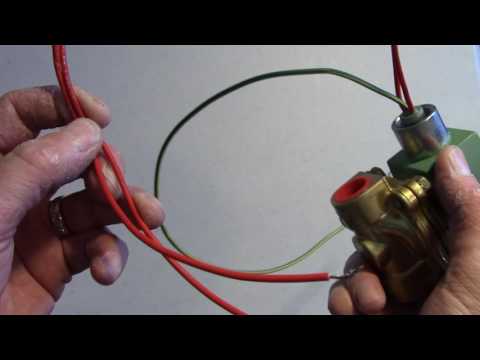
Installing An Asco Solenoid Valve Youtube

Asco joucomatic s engineers have designed a special vcs connector which is fitted onto the valve and into which the profiled 2 wire vcs cable is placed.
Asco 8210g95 120v wiring diagram. It s a very simple process and. Asco solenoid valves are activated by a solenoid electromagnetic coil which when energized or de energized moves the core or piston to apply pressure against its diaphragm and seat. Normally closed operation 1 inch 1 1 4 inch and 1 1 2 inch npt. 2 2 series 2 way 8210 4 12 specifications english units pipe size ins orifice size ins cv flow factor operating pressure differential psi max.
The one where i wire up the solenoid valve so that i can use it with a prop. Asco fluid automation solutions include over 50 000 solenoid and pneumatic valves cylinders and actuators air preparation equipment and accessories. F brass body stainless steel body. Asco solenoid valves control critical flow of air gas water oil and steam in applications spanning numerous industries.
Asco 3 4 npt 120 volt normally closed brass body solenoid valve for water service with a maximum temperature of 180 f and a maximum pressure of 125 psi. Avoid typical problems when installing a solenoid valve. Presented by industrial equipment co. Brass and stainless construction.
Connection system for solenoid valves and spool valves designed for fieldbus systems profibus dp interbus s device net. Installation maintenance instructions i m no v6055r3 3 way miniature sized solenoid valves brass and stainless steel construction series normally closed normally open and universal operation 8320 1 8 npt 3 64 1 16 3 32 and 1 8 orifice notice. Since the kneeling monk prop is largely completed i prepare the solenoid valve for use. View and download asco 8210 series installation and maintenance instructions online.
8210 series control unit pdf manual download. 2 way internal piloted operated solenoid valves. Engineering information solenoid valves ac dc nominal voltage rating normal operating range nominal voltage rating normal operating range 24 20 24 6 5 1 6 3 120 102 120 12 10 2 12 6 24 20 25 240 204 240 120 102 126 480 408 480 240 204 252 inrush amps volt amp inrush voltage holding amps volt amp holding voltage amps watts dc voltage.

Asco 8210g95 120v Wiring Diagram Kuiyt 10balmoond Mooiravenstein Nl
W600 Wiring Solenoid Valves Youtube

73dd Door Wiring Diagram Mercedes E Class Wiring Resources

Section4 1 Valve Switch
Wrg 8282 S1 Wiring Diagram

Solenoid Valves Asco Redhat General Service Miniature

2009 Jeep Grand Cherokee Headlight Wiring Diagram Wiring Diagram

7d3f9f Wiring Diagram For Sterling Trucks Wiring Resources

Wrg 9829 2004 Buick Lesabre Radio Wiring Diagram
Wrg 9303 Toyota Maf Sensor Wiring

5e21b3 Poor Boy Conversion Wiring Diagram Wiring Resources

32d39c Fuse Box 1995 Chevy G20 Wiring Library

Asco Catlog33a Valve Pipe Fluid Conveyance
