0 10 Dimming Ballast Wiring Diagram
Low Voltage Led 0 10v Dimming Usai
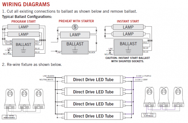
Keystone 0 10v Dimmable Led T8 Tubes Direct Wire Premier Lighting

277v Wiring Diagram Ford 2 Remix Medien De

Cw 5531 Lutron Led Dimmer Switch Wiring Diagram Download Diagram
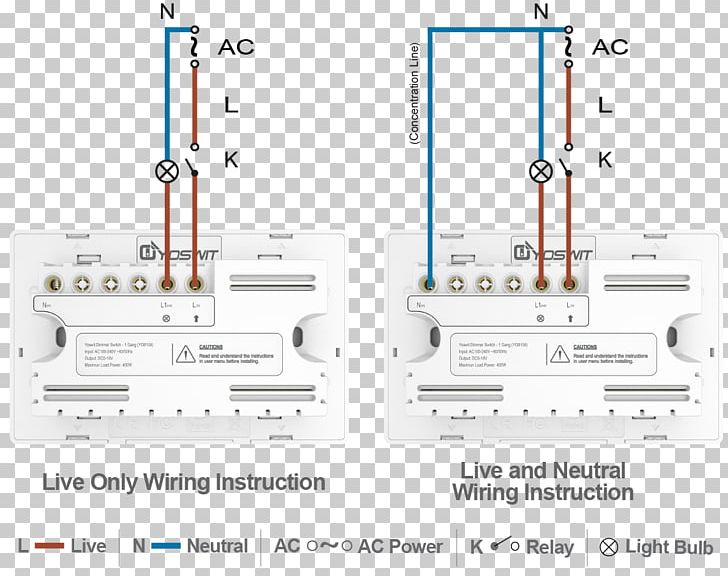
0 10 V Lighting Control Dimmer Wiring Diagram Light Switch

0 10v Dimmer Wiring Diagram Tuli 10balmoond Mooiravenstein Nl

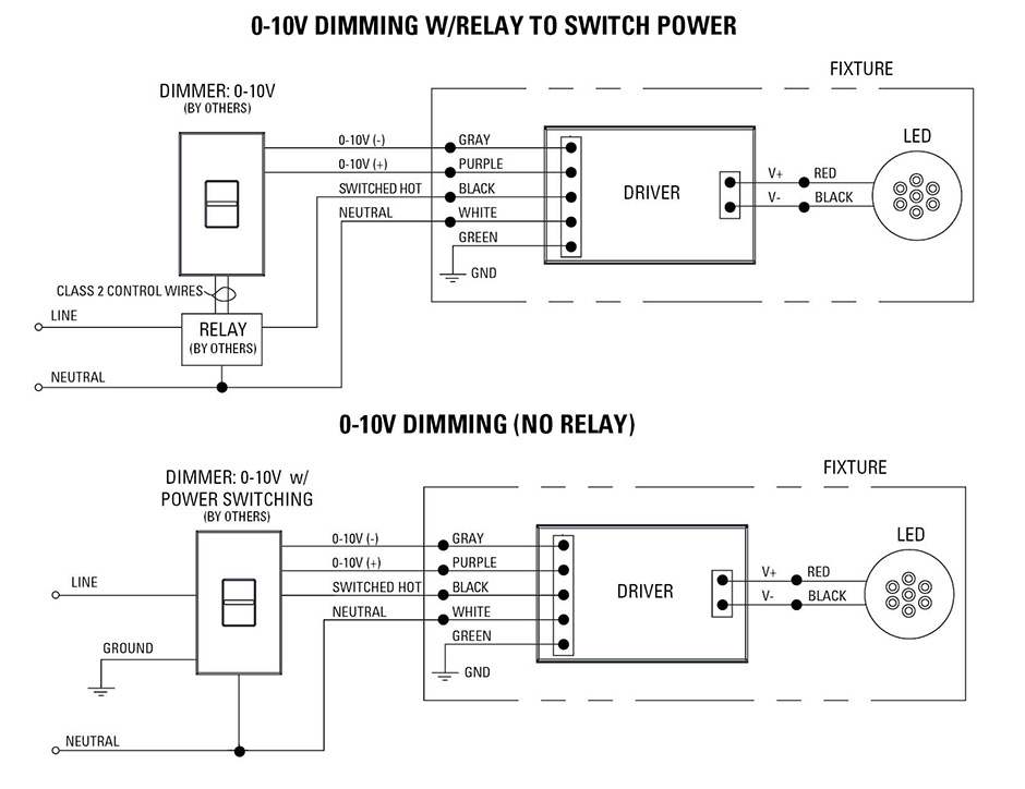
Switched hot neutral vdc positive and.
0 10 dimming ballast wiring diagram. Our standard 0 10v dimming driver option is often provided standard check spec sheets and dims down to 10 at minimum light level. This kind of impression 0 10 volt dimming ballast wiring diagram 0 10v dimming wiring with lutron dimming ballast wiring diagram previously mentioned is actually classed having. Gray dimmer lead to gray connection on ballast. Ballast diagram dimming.
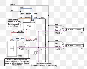
This is a 120v or 277 volt ballast 4435 290 32651 rev. Electronic fluorescent dimming ballast and qualified for iso. Wiring diagram 1 insulating label green ground black white red hot black neutral white line 120 277vac 60hz dimmer gray yellow to lamps red blue 0 10 vdc ballast yellow red 1 3 7 matching remote additional neutral wire 2 dimmer 2 3 4 red violet white yellow red. 0 10v dimming ballast wiring diagram photos pictures range this printed right here had been effectively picked out and also authored by admin just.
0 10v dimming ballast wiring diagram just what s wiring diagram. It is the default dimming driver provided with our warm glow dimming color select and max output product lines among others. A wiring diagram is a streamlined standard photographic representation of an electric circuit. A wiring diagram is a type of schematic which makes use of abstract photographic symbols to reveal all the affiliations of components in a system.
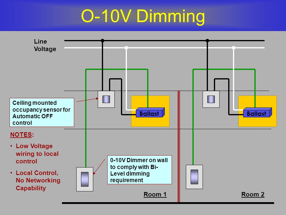
0 10v dimming wiring diagram 0 10v dimmer switch leviton ip710 lfz or equal for other types of dimming control systems consult controls manufacturer for wiring instructions switched hot black switched hot red typical low voltage dimming wires purple gray typical electrical panel hot black typical 120v or 277v 60 hz neutral white. Most people attain the following marvelous photographs from online and choose among the best with regard to you. Dimming fluorescent lights are usually found in commercial and institutional environments and not common in the household. Dimming ballasts are available for fluorescent tubes and cfls that use an external ballast.
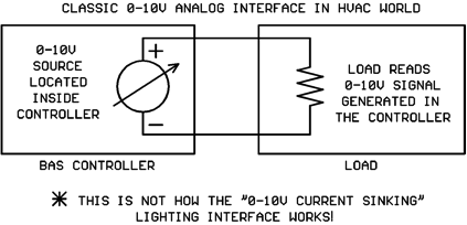
A typical 0 10v wiring diagram is shown below. C similar to any other 0 to 10 volt dimming driver or ballast. Posted by simply tops stars team with january 2 2014. Variety of 0 10v dimming ballast wiring diagram.
It shows the elements of the circuit as simplified shapes and also the power and also signal connections in between the devices. These ballasts are usually rapid start or programmed start and have a good dimming range. Proceed to step 5.

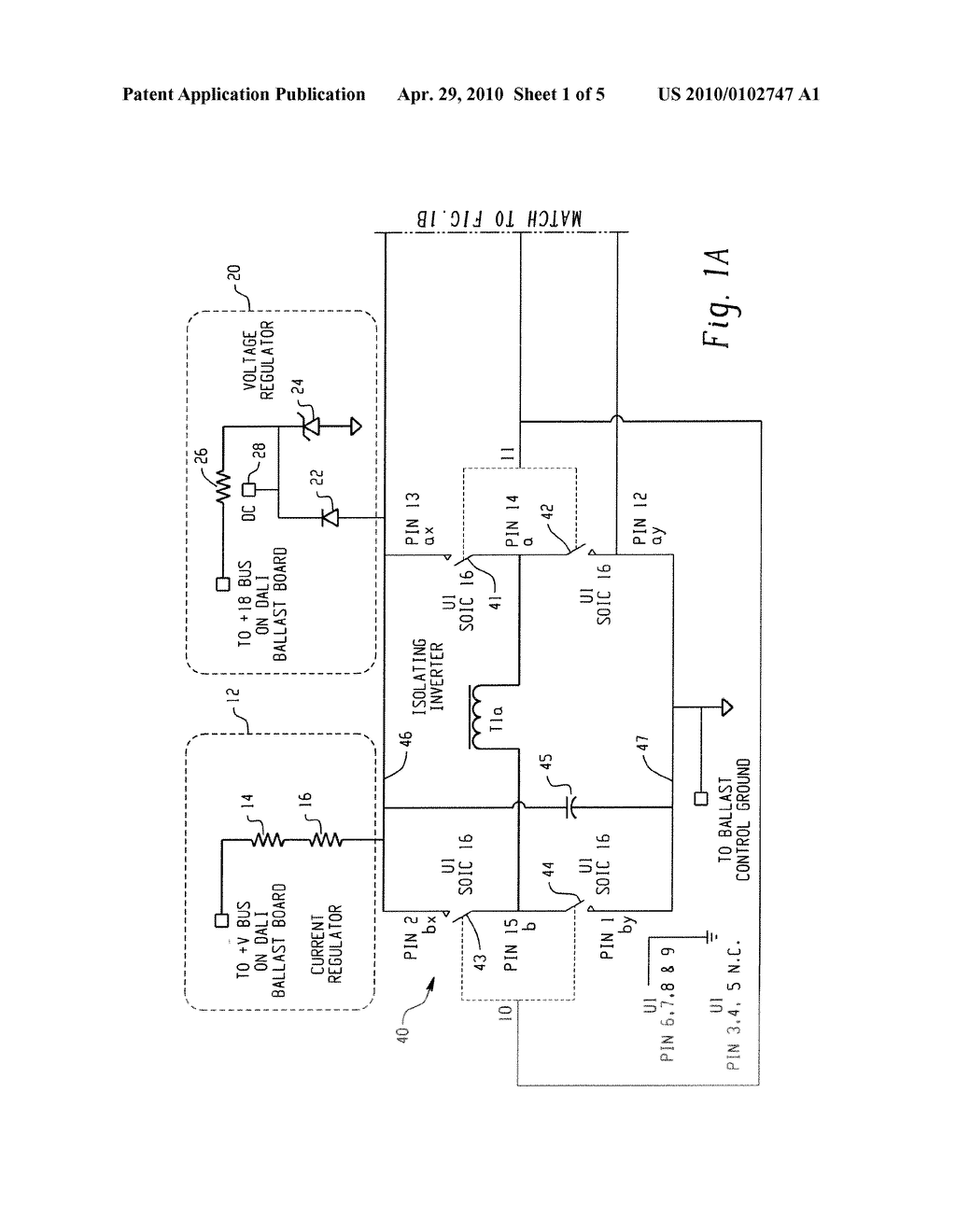
Universal Lighting Technologies Superdim Energy Management

Universal Lighting Technologies Superdim Energy Management

Wb 2239 Watt Stopper Bz 150 Wiring Diagram Get Free Image About
32 0 10 Volt Dimming Wiring Diagram Wiring Diagram List

Cw 5531 Lutron Led Dimmer Switch Wiring Diagram Download Diagram
Brian Liebel Pe Lc Afterimage S P A C E Ppt Download

Of 8381 Wiring Diagram Furthermore Lutron Wiring Diagram On

Led Dimmer Wiring Diagram Gain Repeat24 Klictravel Nl
Electronic Ballast Images Electronic Ballast Transparent Png
Kele S Ldim2 Sheds Light On 0 10v Dimmable Lighting Fixtures
Http Www Lutron Com Technicaldocumentlibrary 048568 Pdf

Nrlbspc6xdjswm
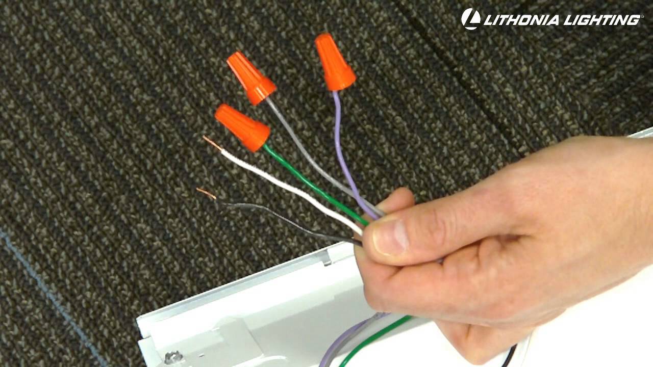
Lithonia Lighting Gtled Dimming Capabilities Youtube
